Router 2611
Method 1: Serial
Requirement: TeraTerm and IOS c2600-a3jk9s-mz.123-11.T.bin
1. Change the serial speed to 115200
rommon 1 >confreg
Configuration Summary
enabled are:
break/abort has effect
console baud: 9600
boot: the ROM Monitor
do you wish to change the configuration? y/n [n]: y
enable “diagnostic mode”? y/n [n]:
enable “use net in IP bcast address”? y/n [n]:
enable “load rom after netboot fails”? y/n [n]:
enable “use all zero broadcast”? y/n [n]:
disable “break/abort has effect”? y/n [n]:
enable “ignore system config info”? y/n [n]:
change console baud rate? y/n [n]: y
enter rate: 0 = 9600, 1 = 4800, 2 = 1200, 3 = 2400
4 = 19200, 5 = 38400, 6 = 57600, 7 = 115200 [0]: 7
change the boot characteristics? y/n [n]:
Configuration Summary
enabled are:
break/abort has effect
console baud: 115200
boot: the ROM Monitor
do you wish to change the configuration? y/n [n]:
You must reset or power cycle for new config to take effect.
2. Reboot the router
rommon 2 >reset
3. Transfer IOS file
Set TeraTerm serial speed to 115200
rommon 2 > xmodem -c c2600-a3jk9s-mz.123-11.T.bin
Click TeraTerm File/Transfer/XModem/Send menu and choose c2600-a3jk9s-mz.123-11.T.bin file
4. Change Serial speed back to 9600
rommon 1 >confreg
Configuration Summary
enabled are:
break/abort has effect
console baud: 115200
boot: the ROM Monitor
do you wish to change the configuration? y/n [n]: y
enable “diagnostic mode”? y/n [n]:
enable “use net in IP bcast address”? y/n [n]:
enable “load rom after netboot fails”? y/n [n]:
enable “use all zero broadcast”? y/n [n]:
disable “break/abort has effect”? y/n [n]:
enable “ignore system config info”? y/n [n]:
change console baud rate? y/n [n]: y
enter rate: 0 = 9600, 1 = 4800, 2 = 1200, 3 = 2400
4 = 19200, 5 = 38400, 6 = 57600, 7 = 115200 [0]: 0
change the boot characteristics? y/n [n]:
Configuration Summary
enabled are:
break/abort has effect
console baud: 9600
boot: the ROM Monitor
do you wish to change the configuration? y/n [n]:
You must reset or power cycle for new config to take effect.
5. Set boot sequence to default
rommon 12 > confreg 0x2102
6. Reboot the router
You must reset or power cycle for new config to take effect
rommon 12 >reset
Method 2: TFTP
rommon 6 > set
rommon 7 > IP_ADDRESS=192.168.1.12
rommon 8 > IP_SUBNET_MASK=255.255.255.0
rommon 9 > DEFAULT_GATEWAY=192.168.1.6
rommon 10 > TFTP_SERVER=192.168.1.6
rommon 11 > TFTP_FILE=c2600-a3jk9s-mz.123-11.T.bin
rommon 12 > tftpdnld
IP_ADDRESS: 192.168.1.12
IP_SUBNET_MASK: 255.255.255.0
DEFAULT_GATEWAY: 192.168.1.6
TFTP_SERVER: 192.168.1.6
TFTP_FILE: c2600-a3jk9s-mz.123-11.T.bin
Invoke this command for disaster recovery only.
WARNING: all existing data in all partitions on flash will be lost!
Do you wish to continue? y/n: [n]: y
Receiving c2600-a3jk9s-mz.123-11.T.bin from 192.168.1.6 !!!!!.!!!!!!!!!!!!!!.!!!!
File reception completed.
Copying file c2600-a3jk9s-mz.123-11.T.bin to flash.
Erasing flash at 0x607c0000
program flash location 0x60440000
SWITCH 3750
download latest IOS that fit into your DRAM and flash
run Tftpd64
copy latest IOS into c:\tftp
-check current IOS version
#dir flash:
Directory of flash:/
2 -rwx 976 Mar 1 1993 00:01:29 +00:00 vlan.dat
3 -rwx 4902 Mar 1 1993 00:26:25 +00:00 config.text
4 -rwx 5493 Mar 1 1993 00:26:26 +00:00 private-config.text
5 -rwx 13010154 May 6 2013 16:15:55 +00:00 c3750-ipservicesk9-mz.122-55.SE7.bin
-delete old firmware because flash not enough
# delete c3750-ipservicesk9-mz.122-55.SE7.bin
#copy tftp: flash:
Address or name of remote host [10.0.10.102]?
Source filename [c3750-ipservicesk9-mz.122-55.SE12.bin]?
Destination filename [c3750-ipservicesk9-mz.122-55.SE12.bin]?
-fix boot-path
(config)#boot system flash:c3750-ipservicesk9-mz.122-55.SE12.bin
#sh boot
BOOT path-list : flash:c3750-ipservicesk9-mz.122-55.SE12.bin
Config file : flash:/config.text
Private Config file : flash:/private-config.text
# wr mem
Cyberoam:
SOURCE: http://kb.cyberoam.com/default.asp?id=1893&SID=&Lang=1
check current OS: http://kb.cyberoam.com/default.asp?id=1882&Lang=1&SID=
-click Check for upgrades
-click “Click here” on top right to download new firmware
-click SYSTEM/Maintenance/Firmware and up arrow on the right bottom
F5:
click Main/System/Archives/Create
to Restore
click System > Archives.
Click the name of the UCS archive you want to restore.
If the UCS archive is encrypted, type the passphrase for the encrypted UCS archive file in the Restore Passphrase field. If the UCS archive is not encrypted, you can skip this step.
To initiate the UCS archive restore process, click Restore.
When the restore process is completed, examine the status page for any reported errors before proceeding to the next step.
To return to the Archive List page, click OK.
If you restored the UCS archive on a different device and received the errors noted in the Considerations for restoring configuration data section of this article, you must reactivate the BIG-IP system license.
After relicensing the system, restart the system to ensure that the configuration is fully loaded. To restart the system, navigate to System > Configuration, and then click Reboot.
If the system you restored contains the FIPS 140 HSM, you must configure the FIPS 140 HSM Security World after completing steps 1 through 9. For additional information about recovering FIPS information after a system recovery, refer to the Configuring and Maintaining a FIPS Security Domain chapter in the Platform Guide: 6900 and 8900.
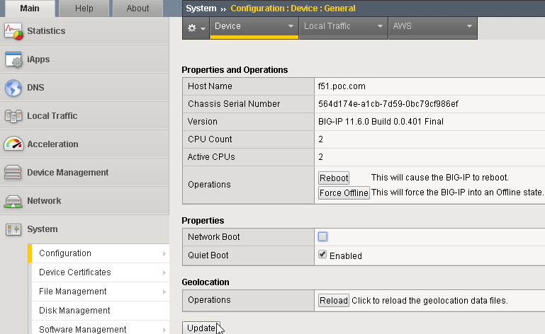
-Check current version
-Check, download latest update

-Disable all resources to save disk. After upgrade you can enable back

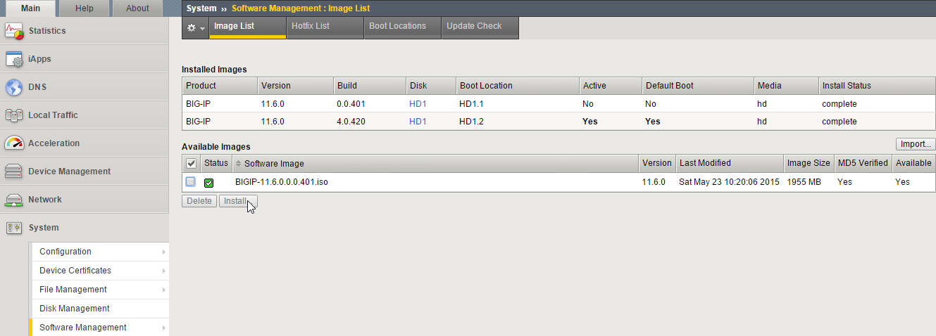
-Download Base iso BIGIP-11.6.0.0.0.401.iso
Check md5 of BIGIP-11.6.0.0.0.401.iso
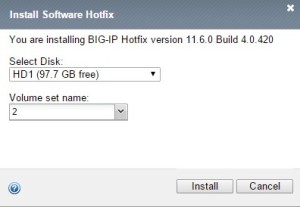
if match then import then install in HD1, in volume name type 2

-Download and import HotFix

-Apply hotfix to HD1 Volume 2
-update Boot Locations to HD1.2

it will reboot automatically
-now the status will be

We will upgrade disk HD1.1 as well
Go to System/Software Management/Hotfix List

-Change boot location back to HD1.1

it will reboot again
-new boot location will be HD1.1

-activate Resource Provisioning

-update OPSWAT
Download the OPSWAT hotfix from the F5 Downloads site.
Note: For instructions about obtaining a hotfix, refer to SOL167: Downloading software from F5.
Log in to the BIG-IP Configuration utility.
Navigate to System > Software Management.
Click Antivirus Check Updates.
NOTE: Antivirus Check Updates will appear if “Access Policy (APM)” is enabled in System/Resource Provisioning
Click Upload Package.
Click Browse.
Select the file you downloaded in step 1.
From the Install Option menu, select the appropriate installation option.
Note: The Do not Install option uploads the EPSEC package without installing it.
If you selected the Install on Autosync enabled Device Group option, select the device group from the Device Group menu.
Click Upload.
After the software uploads, click OK.
Note: The upload process may take a couple of minutes.
BIG-IP APM is now running the OPSWAT package. To confirm that the installation was successful, review the Installed Version field under the Device EPSEC Status tab.
-update ip-geolocation
SOURCE: https://support.f5.com/kb/en-us/solutions/public/11000/100/sol11176.html
upload ip-geolocation-1.0.1-20150403-132.0.zip ip-geolocation-1.0.1-20150403.132.0.zip.md5 and by scp into F5 /shared/tmp
#md5sum -c ip-geolocation-1.0.1-20150403.132.0.zip.md5
ip-geolocation-1.0.1-20150403.132.0.zip: OK
#unzip ip-geolocation-1.0.1-20150403.132.0.zip
Archive: ip-geolocation-1.0.1-20150403.132.0.zip
inflating: geoip-data-Region2-1.0.1-20150403.132.0.i686.rpm
inflating: geoip-data-ISP-1.0.1-20150403.132.0.i686.rpm
inflating: geoip-data-Org-1.0.1-20150403.132.0.i686.rpm
inflating: geoip-data-v6-1.0.1-20150403.132.0.i686.rpm
inflating: README.txt
# geoip_update_data -f /shared/tmp/geoip-data-ISP-1.0.1-20150403.132.0.i686.rpm
# geoip_update_data -f /shared/tmp/geoip-data-Org-1.0.1-20150403.132.0.i686.rpm
# geoip_update_data -f /shared/tmp/geoip-data-Region2-1.0.1-20150403.132.0.i686.rpm
# geoip_update_data -f /shared/tmp/geoip-data-v6-1.0.1-20150403.132.0.i686.rpm
Verify that the geolocation database was loaded
#geoip_lookup -f /shared/GeoIP/F5GeoIPOrg.dat 202.137.3.120
Will attempt to lookup ip ‘202.137.3.120’
opening database in /shared/GeoIP/F5GeoIPOrg.dat
size of geoip database = 200571145, segments = 10065614, version = GEO-148 20150403 Build 1 Copyright (c) F5 Networks Inc All Rights Reserved
geoip_seek = 0698e0cf
geoip record ip = 202.137.3.120
name = isp linknet(tmos)# show sys software status
————————————————————-
Sys::Software Status
Volume Product Version Build Active Status
————————————————————-
HD1.116040420hf4 BIG-IP 11.6.0 4.0.420 yes complete
HD1.1 BIG-IP 11.6.0 0.0.401 no complete
HD1.2 none none none no completeFortiNet:
Always follow upgrade paths from the release notes
# get system status
Version: FortiWiFi-80CM v5.2.3,build0670,150318 (GA)
Virus-DB: 16.00560(2012-10-19 08:31)
Extended DB: 1.00000(2012-10-17 15:46)
IPS-DB: 5.00555(2014-10-07 01:21)
IPS-ETDB: 0.00000(2001-01-01 00:00)
Serial-Number: FW80CM3909633470
Botnet DB: 1.00000(2012-05-28 22:51)
BIOS version: 04000006
Log hard disk: Not available
Internal Switch mode: switch
Hostname: FW80CM3909633470
Operation Mode: NAT
Current virtual domain: root
Max number of virtual domains: 10
Virtual domains status: 1 in NAT mode, 0 in TP mode
Virtual domain configuration: disable
FIPS-CC mode: disable
Current HA mode: standalone
WiFi Chipset: Ralink RT2860
WiFi firmware version: 2.1.3.0
Branch point: 670
Release Version Information: GA
System time: Fri May 1 17:51:12 2015
-Backup current config
go to System/Maintenance/Backup & Restore
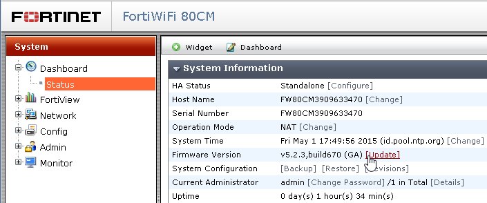
-Upgrade firmware
go to System/Status
click Firmware Version/Update
HP:
SOURCE: http://evilrouters.net/2009/02/02/upgrading-procurve-firmware-via-tftp/
Download new firmware from
run SolarWinds TFTP server
ProCurve Switch 3400cl-24G# sh ver
Image stamp: /sw/code/build/makf(ts_08_5)
Dec 21 2005 12:12:48
M.08.86
1513
Boot Image: Primary
# sh flash
Image Size(Bytes) Date Version
—– ———- ——– ——-
Primary Image : 3325207 12/21/05 M.08.86
Secondary Image : 3325207 12/21/05 M.08.86
Boot Rom Version: I.08.07
Current Boot : Primary
(config)# password manager user-name admin
New password for Manager: admin
Please retype new password for Manager: admin
(config)# time 11/23/14
Sun Nov 23 00:33:23 2014
(config)# time 23:10
Sun Nov 23 23:10:38 2014
(config)# time timezone +7
(config)# crypto key generate ssh
Installing new RSA key. If the key/entropy cache is
depleted, this could take up to a minute.
#write mem
(config)# ip ssh
(config)# ip ssh filetransfer
(config)# sh ip ssh
SSH Enabled : Yes
SSH Version : 2
IP Port Number : 22
Timeout (sec) : 120
Server Key Size (bits) : 1024
Secure Copy Enabled : Yes
Ses Type | Protocol Source IP and Port
— ——– + ——— ———————
1 console |
2 inactive |
3 inactive |
4 inactive |
(config)# setup
3400CLve 23-Nov-2014 23:34:31
==========================- CONSOLE – MANAGER MODE -============================
Switch Setup
System Name : 3400CL
System Contact :
Manager Password : ******** Confirm Password : ********
Logon Default : CLI Time Zone [0] : 7
Community Name : public Spanning Tree Enabled [No] : No
Default Gateway : 10.0.0.1
Time Sync Method [None] : TIMEP
TimeP Mode [Disabled] : Disabled
IP Config [DHCP/Bootp] : Manual
IP Address : 10.0.0.253
Subnet Mask : 255.255.255.0
Actions-> Cancel Edit Save Help
Enter System Name – up to 25 characters.
Use arrow keys to change field selection, to toggle field choices,
(config)# copy tftp flash 10.0.0.250 M_10_10.swi secondary
The Secondary OS Image will be deleted, continue [y/n]? y
(config)# sh flash
Image Size(Bytes) Date Version
—– ———- ——– ——-
Primary Image : 3325207 12/21/05 M.08.86
Secondary Image : 3558382 06/26/06 M.10.10
Boot Rom Version: I.08.07
Current Boot : Primary
(config)# boot system flash secondary
# copy tftp flash 10.0.0.250 M_10_102.swi secondary
The Secondary OS Image will be deleted, continue [y/n]? y
# copy tftp flash 10.0.0.250 M_10_10.swi primary
The Primary OS Image will be deleted, continue [y/n]?
(config)# boot system flash primary
# copy tftp flash 10.0.0.250 M_10_102.swi primary
The Primary OS Image will be deleted, continue [y/n]? y
# sh flash
Image Size(Bytes) Date Version
—– ———- ——– ——-
Primary Image : 3856932 04/09/14 M.10.102
Secondary Image : 3856932 04/09/14 M.10.102
Boot Rom Version: I.08.12
Current Boot : PrimaryJuniper:
Download recommended image from
1. SRX210 Upgrade example
> show version
Hostname: srx1
Model: Dell J-SRX210H-POE
JUNOS Software Release [10.3R2.11]
2. verify image md5
% md5 /var/tmp/junos-srxsme-11.4R11.4-domestic.tgz
MD5 (/var/tmp/junos-srxsme-11.4R11.4-domestic.tgz) = 6a19bc0ceac9913c053a90214ee61cb1
3. backup config
Back up the currently running and active file system so that you can recover to
a known, stable environment in case something goes wrong with the upgrade.
> request system snapshot
The /root file system is backed up to /altroot, and /config is backed up to
/altconfig. The /root and /config file systems are on the router’s flash disk, and
the /altroot and /altconfig file systems are on the router’s hard disk.
Roll back to previously installed version:
>request system software rollback
4. copy files
Copy the jinstall package to the router. We recommend that you copy it to the
/var/tmp directory, which is a large file system on the hard disk.
you can check the diskspace with
>show system storage
1st method using SCP:
I used a secure copy:
>scp jinstall-8.4R2.3-domestic-signed.tgz andree@some-router.bc.net:/var/tmp/
2nd method using usb pen drive:
% ls /dev/da*
/dev/da0 /dev/da0s1c /dev/da0s2c /dev/da0s3e /dev/da0s4a
/dev/da0s1 /dev/da0s2 /dev/da0s3 /dev/da0s3f /dev/da0s4c
/dev/da0s1a /dev/da0s2a /dev/da0s3c /dev/da0s4
root@srx1% umass1: Verbatim STORE N GO, rev 2.10/a.00, addr 4
da1 at umass-sim1 bus 1 target 0 lun 0
da1: Removable Direct Access SCSI-6 device
da1: 40.000MB/s transfers
da1: 30400MB (62259200 512 byte sectors: 255H 63S/T 3875C)root@srx1% ls /dev/da*
/dev/da0 /dev/da0s2 /dev/da0s3c /dev/da0s4a /dev/da1s2
/dev/da0s1 /dev/da0s2a /dev/da0s3e /dev/da0s4c
/dev/da0s1a /dev/da0s2c /dev/da0s3f /dev/da1
/dev/da0s1c /dev/da0s3 /dev/da0s4
%mount -t msdosfs /dev/da1s2 /mnt
5. Install the new software package
Install the new software package, as shown below, where package-name is the
full filename.
> request system software add /mnt/jinstall-ex-2200-12.3R8.7-domestic-signed.tgz
For a software package on a remote server:
ftp://hostname/pathname/package.tgz
tftp://hostname/pathname/package.tgz
or local attached usb drive
If you encounter “Not enough space in /var to save the package file”
> request system software add no-validate no-copy /mnt/jinstall-ex-2200-12.3R8.7-domestic-signed.tgz
%umount /mnt
Copy primary partition to usb if needed
> request system snapshot media usb partition
Clearing current label…
Partitioning usb media (/dev/da1) …
Partitions on snapshot:
Partition Mountpoint Size Snapshot argument
s1a /altroot 2.4G none
s2a / 2.4G none
s3e /config 185M none
s3f /var 2.1G none
s4a /recovery/software 224M none
s4e /recovery/state 15M none
Copying ‘/dev/da0s1a’ to ‘/dev/da1s1a’ .. (this may take a few minutes)
Copying ‘/dev/da0s2a’ to ‘/dev/da1s2a’ .. (this may take a few minutes)
Copying ‘/dev/da0s3e’ to ‘/dev/da1s3e’ .. (this may take a few minutes)
Copying ‘/dev/da0s3f’ to ‘/dev/da1s3f’ .. (this may take a few minutes)
Copying ‘/dev/da0s4e’ to ‘/dev/da1s4e’ .. (this may take a few minutes)
Copying ‘/dev/da0s4a’ to ‘/dev/da1s4a’ .. (this may take a few minutes)
The following filesystems were archived: /altroot / /config /var /recovery/state /recovery/software
6. Reboot the router to start the new software:
>request system reboot
7. verify new software
Log in and verify the version of software running after the router reboots. Issue
>show version
8. request system snapshot
After you have upgraded or downgraded the software and are satisfied that the new software is successfully running, issue the request system snapshot command to back up the new software.
NOTE: After you issue the request system snapshot command, you cannot return to the previous version of the software, because the running copy and backup copy of the software are identical.
Once the software is installed and the switch has booted into the new version of Junos, be sure to copy the contents of the primary root partition to the alternate root partition so that the switch boots the same version of Junos regardless of which root partition it has booted from.
Copy primary partition to secondary one
> request system snapshot slice alternate
Formatting alternate root (/dev/da0s2a)…
Copying ‘/dev/da0s1a’ to ‘/dev/da0s2a’ .. (this may take a few minutes)
The following filesystems were archived: /
9. Verify new version
> show version
Hostname: srx1
Model: Dell J-SRX210H-POE
JUNOS Software Release [11.4R11.4]
EX2200 Upgrade Example:
-connect ethernet to Management port me0, and set ip address, allow ssh
-download jinstall
% md5 /var/tmp/jinstall-ex-2200-12.3R6.6-domestic-signed.tgz
> show version
Model: ex2200-24t-4g
JUNOS Base OS boot [11.4R1.6]
JUNOS Base OS Software Suite [11.4R1.6]
JUNOS Kernel Software Suite [11.4R1.6]
JUNOS Crypto Software Suite [11.4R1.6]
JUNOS Online Documentation [11.4R1.6]
JUNOS Enterprise Software Suite [11.4R1.6]
JUNOS Packet Forwarding Engine Enterprise Software Suite [11.4R1.6]
JUNOS Routing Software Suite [11.4R1.6]
JUNOS Web Management [11.4R1.6]
> request system snapshot media external partition
> request system software add /var/tmp/jinstall-ex-2200-12.3R6.6-domestic-signed.tgz validate
> request system reboot
> show version
fpc0:
————————————————————————–
Model: ex2200-24t-4g
JUNOS Base OS boot [12.3R6.6]
JUNOS Base OS Software Suite [12.3R6.6]
JUNOS Kernel Software Suite [12.3R6.6]
JUNOS Crypto Software Suite [12.3R6.6]
JUNOS Online Documentation [12.3R6.6]
JUNOS Enterprise Software Suite [12.3R6.6]
JUNOS Packet Forwarding Engine Enterprise Software Suite [12.3R6.6]
JUNOS Routing Software Suite [12.3R6.6]
JUNOS Web Management [12.3R6.6]
JUNOS FIPS mode utilities [12.3R6.6]
{master:0}
10. if not enough space in device
>request system storage cleanup
if still not enough
After the cleanup, if there is still not enough space for the upgrade, perform the following procedure:
>start shell
%find -x /cf/var -type f -exec du -k {} \; | sort –n
Delete the files at the end of the above generated output. Here is an example:
18256 /cf/var/lost+found/#11136/flowd_octeon.core.1.gz
19600 /cf/var/lost+found/#11136/flowd_octeon.core.0.gz
The first column displays the file size in kilobytes and the second column displays the file location.
You can also find files, which are greater in than the specific value. For example, the following command will show files whose size will be more than 10MB:
%sh -c ‘find / -size +10485760c 2> /dev/null’ | xargs du -h | sort -nrto check the size after cleanup
# run show system storage partitions
Boot Media: internal (da0)
Active Partition: da0s2a
Backup Partition: da0s1a
Currently booted from: active (da0s2a)
Partitions information:
Partition Size Mountpoint
s1a 293M altroot
s2a 293M /
s3e 24M /config
s3f 342M /var
s4a 30M recovery
11. if upgrade from LOADER needed
To recover or install from USB, make sure that the USB media is ScanDisk formatted, with booting packages installed. You can use the USB storage that is provided with your Juniper equipment
-format usb in fat32
copy image jinstall-10.4R11.4-domestic-signed.tgz into it
-Power on the switch. The loader script starts; after Loading /boot/defaults/loader.conf is displayed, you are prompted with:
Hit [Enter] to boot immediately, or space bar for command prompt.
Press the space bar to enter the manual loader. The loader> prompt is displayed.
Note: There is a 1 second delay for pressing the space bar.
-Type the following command:
If from USB
If from TFTP
install source tftp://192.17.1.28/junos/jinstall-10.4R11.4-domestic-signed.tgz
The Junos package on a USB device is commonly stored in the root drive as the only file. For example:
install source file:///jinstall-10.4R11.4-domestic-signed.tgz
Mikrotik:
-login to WinBox
-click Files
-download all_packages-mipsbe-6.15.zip from mikrotik.com
-extract it and drag it into Files window
-click System/Reboot
-check package version in System/Packages
-download latest firmware
click System/RouterBoard/Upgrade
or System/Packages/Check System Update
Downgrade
/system package downgradeNetApp:
UPGRADE ONTAP
-go to your
http://support.netapp.com/NOW/asuphome/
click Search, and put filer S/N
click Upgrade Advisor
This upgrade plan is based on AutoSupport received on Jan 05 03:06:54 2013(UA version:5.1.8)Related to Warnings DescriptionUpgradeThe VLD protocol is licensed on this node and ONTAP 8.1.2 does not support VLDs. If VLDs exist on this system, SnapDrive must be upgraded to at least version 3 and the VLDs must be converted to iSCSI LUNs
UpgradeAt least one volume or aggregate is not online. They must be onlined before proceeding with the upgrade. If you proceed, that data will be unavailable and the ability to revert the system will be compromised. Volumes not online: [sis,sis].
UpgradeNetApp Global Services recommends running perfstat(
http://support.netapp.com/NOW/download/tools/perfstat/) during a typical usage time to save a performance baseline prior to an upgrade in case it is needed. This will take about 30 mins of run time.
UpgradeFor each HA pair, you should plan for approximately 30 minutes to complete preparatory steps, 60 minutes to perform the upgrade, and 30 minutes to complete post-upgrade steps.
UpgradeYou must ensure that CPU utilization does not exceed 50% before beginning a NDU upgrade
UpgradePlease check the risk details for your system here(
http://support.netapp.com/willows/pri/system.do?serialNo=850000185621&tool=ars) that might impact your upgrade.
Down gradeAt least one volume or aggregate is not online. They must be onlined before proceeding with the upgrade. If you proceed, that data will be unavailable and the ability to revert the system will be compromised. Volumes not online: [sis,sis].
StepUpgrade Plan – Data ONTAP 8.1.1 7-Mode –> 8.1.21Be sure to read the Release Notes as well as the Upgrade Guide of the Data ONTAP 8.1.2(
http://support.netapp.com/NOW/download/software/ontap/8.1.2) for important information and technical detail before beginning your upgrade.1. Before upgrading Data ONTAP, monitor CPU and disk utilization for 30 seconds by entering the following command at the console of each storage controller:
sysstat -c 10 -x 3
The values in the CPU and Disk Util columns are strongly recommended not to exceed 50% for all ten measurements reported. Ensure that no additional load is added to the storage system until the upgrade completes.
Download perfstat and run it on a client as follows:
perfstat -f filername -t 4 -i 5 > perfstatname.out
Save this output file for a couple of weeks after the upgrade is complete
2. Upgrade SnapDrive on all VLD clients to version 3 or higher
3. Download the system files for 8.1.2 (812_q_image.tgz) from the Support Site(
http://support.netapp.com/NOW/download/software/ontap/8.1.2). Be sure to download the system files that match your node model.
If you are performing a Data ONTAP NDU (or backout), you must perform this step on both nodes before performing the takeover and giveback steps.
4. Verify the checksum of the image file with the value on the Support site(
http://support.netapp.com/NOW/download/software/ontap/8.1.2/checksums.shtml).
5. Connect to the console of the node and trigger an AutoSupport:
FAS-c1> options autosupport.doit “starting_NDU 8.1.2”
6. Contact NetApp Support and check /etc/messages for any obvious errors; e.g. disk errors, firmware errors, etc.
Using Windows: Map C$ to the Windows Host
Browse the etc folder
Open file ‘messages’ using WordPad. If failed disks are found, it is recommended they be removed before upgrading.
7. Back up the etc\hosts and etc\rc files in Windows to a temporary directory.
8. Copy the system image file (812_q_image.tgz) to the /etc/software directory on the node. From a Windows box as an Administrator:
o Map the C$ share to a Windows drive letter (for example
X:). \\netappctrlip\C$ and login as PMO\administrator
o Copy the image file to X:\etc\software
9. Install the system file via the software command:
FAS-c1> software update 812_q_image.tgz -r
If you are performing a Data ONTAP NDU (or backout), you must perform this step on both nodes before performing the takeover and giveback steps
10. Check to see if the boot device has been properly updated:
FAS-c1> version
kernel should be 8.1.2.
11. Terminate CIFS on the node to be taken over ( FAS-c2 ):
FAS-c2> cifs terminate
12. For each destination volume, enter the following command to allow existing SnapMirror relations to complete:
FAS-c1> snapmirror quiesce Your Destination here Example
To quiesce relations to the destination volume fas270cl1-cn:vol1, enter the following command:
FAS-c1> snapmirror quiesce fas270cl1-cn:vol1 Enter the following command on both source and destination systems to disable SnapMirror operations:
FAS-c1> snapmirror off
13. Takeover and giveback sequence between nodes.
Terminate CIFS on the node to be taken over (FAS-c2) for all vfilers by running the following command:
FAS-c2> vfiler run * cifs terminate
From FAS-c1, take over the data service from the partner node FAS-c2
FAS-c2> halt
FAS-c2> update_flash
FAS-c2> bye
After FAS-c2 reboots and displays “waiting for giveback”, give back the data service:
FAS-c1> cf giveback Terminate CIFS on the node to be taken over ( FAS-c1 ):
Wait 8 minutes before proceeding to the next step.
FAS-c1> options autosupport.doit “starting_Upgrade 8.1.2”
FAS-c1> cifs terminate From the newly upgraded node FAS-c2, take over the data service from FAS-c1
FAS-c1> halt
FAS-c1> update_flash
FAS-c1> bye
FAS-c2> cf giveback
FAS-c2>
Attention: The giveback is not initiated and an error message is returned if any conditions such as the following are detected:
– open client sessions (such as CIFS sessions)
– long-running operations
– operations that cannot be restarted (such as tape backup or SyncMirror resynchronization)
– error conditions (such as disk connectivity mismatch between the nodes)If giveback is not initiated, complete the following steps:
1. Address the condition described in the error message, ensuring that any identifiedoperations are terminated gracefully.
2. Enter the cf giveback command with the -f option:
cf giveback -f
For more information about the -f option, see the cf(1) man page.14. Enter the following command to re-enable SnapMirror:
FAS-c1> snapmirror on
Enter the following command to resume existing SnapMirror relations:
FAS-c1> snapmirror resume Your Destination here
15. Verify the upgrade completed successfully to Data ONTAP 8.1.2:
FAS-c1> version
16. Upgrade FAS-c2 (if not already done)
17. Use SnapDrive to convert all VLDs to LUNs
18. Connect to the console of the node and trigger an AutoSupport
FAS-c1> options autosupport.doit “finishing_NDU 8.1.2”
StepBackout Plan – Data ONTAP 8.1.2 –> 8.1.1 7-Mode1Download the system files for 8.1.1 7-Mode (811_q_image.tgz) from the Support Site(
http://support.netapp.com/NOW/download/software/ontap/8.1.1). Be sure to download the system files that match your node model.If you are performing a Data ONTAP NDU (or backout), you must perform this step on both nodes before performing the takeover and giveback steps.2Verify the checksum of the image file with the value on the Support site(
http://support.netapp.com/NOW/download/software/ontap/8.1.2/checksums.shtml).
3. Connect to the console of the node and trigger an AutoSupport:
FAS-c1> options autosupport.doit “starting_NDU 8.1.1 7-Mode”
4. Contact NetApp Support and check /etc/messages for any obvious errors; e.g. disk errors, firmware errors, etc.
Using Windows: Map C$ to the Windows Host
Browse the etc folder
Open file ‘messages’ using WordPad. If failed disks are found, it is recommended they be removed before upgrading.
5. Back up the etc\hosts and etc\rc files in Windows to a temporary directory.
6. Copy the system image file (811_q_image.tgz) to the /etc/software directory on the node. From a Windows box as an Administrator:
o Map the C$ share to a Windows drive letter (for example X:).
o Copy the image file to X:\etc\software
7. Install the system file via the software command:
FAS-c1> software update 811_q_image.tgz -r
If you are performing a Data ONTAP NDU (or backout), you must perform this step on both nodes before performing the takeover and giveback steps.
8. Check to see if the boot device has been properly updated:
FAS-c1> version
kernel should be 8.1.1 7-Mode.
9. Takeover and giveback sequence between nodesFrom FAS-c1, take over the data service from the partner node FAS-c2
FAS-c1> cf takeover
Wait 10 minutes before proceeding to the next step.
Doing so ensures the following conditions:
– The node that has taken over is serving data to the clients.
– Applications on the clients have recovered from the pause in I/O that occurs during takeover.
– Load on the storage system has returned to a stable point.
– Multipathing (if deployed) has stabilized.
After FAS-c2 reboots and displays “waiting for giveback”, give back the data service:
FAS-c1> cf giveback From the newly upgraded node FAS-c2, take over the data service from FAS-c1
FAS-c2> cf takeover
Wait 10 minutes before proceeding to the next step.
Doing so ensures the following conditions:
– The node that has taken over is serving data to the clients.
– Applications on the clients have recovered from the pause in I/O that occurs during takeover.
– Load on the storage system has returned to a stable point.
– Multipathing (if deployed) has stabilized.
After the first node reboots and displays “waiting for giveback”, give back the data service:
FAS-c2> cf givebackAttention: The giveback is not initiated and an error message is returned if any conditions such as the following are detected:
– open client sessions (such as CIFS sessions)
– long-running operations
– operations that cannot be restarted (such as tape backup or SyncMirror resynchronization)
– error conditions (such as disk connectivity mismatch between the nodes)If giveback is not initiated, complete the following steps:
1. Address the condition described in the error message, ensuring that any identifiedoperations are terminated gracefully.
2. Enter the cf giveback command with the -f option:
cf giveback -f
For more information about the -f option, see the cf(1) man page.
10. Verify the backout completed successfully to Data ONTAP 8.1.1 7-Mode:
FAS-c1> version
11. Connect to the console of the node and trigger an AutoSupport
FAS-c1> options autosupport.doit “finishing_NDU 8.1.1 7-Mode”
UPGRADE DISK SHELF
download disk shelf fw from
For FAS3240 is IOM3, can be seen from the back of FAS3240
Extract the .ZIP or .TAR image
Copy the .SFW file and the .FVF file if present to the /etc/shelf_fw
make sure options shelf.fw.ndu.enable must be set to “ON”
it will upgrade disk shelf when rebooting
> sysconfig -v
check
Shelf 0: IOM3 Firmware rev. IOM3 A: 0152 IOM3 B: 0152
Shelf 1: IOM3 Firmware rev. IOM3 A: 0152 IOM3 B: 0152
Shelf 2: IOM3 Firmware rev. IOM3 A: 0152 IOM3 B: 0152
UPGRADE SERVICE PROCESSOR
For new ONTAP 8.2
ATTENTION: Whenever a controller is updated to Data ONTAP 8.2 or later, the SP firmware is automatically updated (by default) to the SP firmware package which is bundled with Data ONTAP. No additional manual steps are normally required. The following download/installation instructions only apply if there is a need to update the SP to a firmware package which is different from that bundled with Data ONTAP
-download “Service Processor Image for installation from the Data ONTAP prompt” from
and copy into /etc/software
> software install SP_FW.zip
> sp update
> sp status
UPGRADE IMAGE BIOS
-download from
|
Step
|
Action
|
| 1 |
Click on 30802322.zip to download the file from the NetApp Support Site, and save the file as 30802322.zip on your Web server. |
| 1a |
If you are running in 7-Mode, at the storage system prompt, enter the following command to download the file from your Web server to your storage controller:
software install http://web_server/path/30802322.zip
where web_server is the name or IP address of your Web server, and path is location of the file on your Web server.
The following messages will appear:
software: copying to 30802322.zip
software: 100% file read from location.
software: /etc/software/30802322.zip has been copied.
software: installing software, this could take a few minutes...
software: installation of 30802322.zip completed. |
Installing the BIOS image
To install the BIOS image on your storage controller, complete the following steps:
|
Step
|
Action
|
| 1 |
At the storage system prompt, enter the following command to list the contents of the boot device:
| If you are using… |
Then run the following command… |
| Data ONTAP 7-Mode |
version -b |
| Data ONTAP Cluster-Mode |
run local version -b |
|
| 2 |
At the storage system prompt, enter the following command to determine the BIOS version on your storage controller:
| If you are using… |
Then run the following command… |
| Data ONTAP 7-Mode |
sysconfig -a |
| Data ONTAP Cluster-Mode |
run local sysconfig -a |
Make a note of the BIOS version from the resulting output. |
| 3 |
At the storage system prompt, enter the following command to set your privilege level:
| If you are using… |
Then run the following command… |
| Data ONTAP 7-Mode |
To set your privilege level to advanced, enter:
priv set advanced |
| Data ONTAP Cluster-Mode |
To set your privilege level to diagnostic, enter:
set -privilege diagnostic |
|
| 4 |
At the storage system prompt, enter the following command to update the boot device:
| If you are using… |
Then run the following command… |
| Data ONTAP 7-Mode |
download -d
The following message will appear upon completion of the update:
[download.requestDone:notice]: Operator requested download completed
Note: The update process can take a few minutes. |
| Data ONTAP Cluster-Mode |
system firmware download -package http://web_server/path/30802322.zip
where web_server is the name or IP address of your Web server, and path is the location of the file on your Web server.
The following prompts will appear, allowing you to supply a user name and password to access your Web server (if applicable):
Enter User:
Enter Password:
The following messages will appear:
Firmware download started.
Unpacking package contents.
Firmware downloaded
A reboot followed by an 'update_flash' command at the firmware prompt is required for the downloaded firmware to take effect.
Note: The update process can take a few minutes. |
|
| 5 |
At the storage system prompt, enter the following command to list the updated contents of the boot device:
| If you are using… |
Then run the following command… |
| Data ONTAP 7-Mode |
version -b |
| Data ONTAP Cluster-Mode |
run local version -b |
Verify that the output includes Firmware 5.2. |
| 6 |
If BIOS version identified in Step 2 is… |
Then… |
| 5.2 |
Your storage controller has the current version of BIOS. You do not need to proceed any further. |
| Earlier than 5.2 |
Go to Step 7. |
| 7 |
At the storage system prompt, enter the following command to reboot your storage controller:
| If you are using… |
Then run the following command… |
| Data ONTAP 7-Mode |
reboot |
| Data ONTAP Cluster-Mode |
reboot local |
|
| 8 |
The BIOS will perform an auto firmware update if the AUTO_FW_UPDATE is set to true. Verify the BIOS revision by performing the following ONTAP command to verify the current running BIOS revision.
| If you are using… |
Then run the following command… |
| Data ONTAP 7-Mode |
sysconfig -b |
| Data ONTAP Cluster-Mode |
run local sysconfig -b |
|
|
NetScaler:
STANDALONE
login: nsroot
Password: nsroot
Last login: Mon Mar  26 03:37:27 2008 from 10.102.29.9
Done
> save config
> shell
Last login: Mon Mar  26 03:51:42 from 10.103.25.64
root@NSnnn# cd /var/nsinstall
root@NSnnn# cd 10nsinstall
root@NSnnn# mkdir build_53
root@NSnnn# cd build_53
root@NSnnn# ftp ... get build-10.0-53.5_nc.tgz
root@NSnnn# get ns-10.0-53.5-doc.tgz
root@NSnnn# tar xzvf build-10.0-53.5_nc.tgz
root@NSnnn# ./installns
installns version (10.0-53.5) kernel (ns-10.0-53.5_nc.gz)
...
...
...
Copying ns-10.0-53.5_nc.gz to /flash/ns-10.0-53.5_nc.gz ...

Installing documentation...
...
...
...
Installation has completed.

Reboot NOW? [Y/N] Y
To upgrade a standalone NetScaler running release 8.1, 9.0, 9.1, 9.2, 9.3 by using the configuration utility
- In a Web browser, type the IP address of the NetScaler, such as http://10.102.29.50.
- In User Name and Password, type the administrator credentials.
- In Start in, select Configuration, and then click Login, as shown in the following figure.
- In the configuration utility, in the navigation pane, click System.
- In the System Overview page, click Upgrade Wizard.
- Follow the instructions to upgrade the software.
- When prompted, select Reboot.
Note: After the upgrade, close all browser instances and clear your computer’s cache before accessing the appliance.
HA
Upgrading a High Availability Pair
Updated: 2012-03-17
To upgrade the system software on NetScaler units in a high availability pair, you need to upgrade the software first on the secondary node and then on the primary node.
To upgrade NetScaler units in a high availability pair running release 8.1, 9.0, 9.1, 9.2, 9.3 by using the NetScaler command line
Machine A is the primary node and machine B is the secondary node before the upgrade.On machine B (original secondary node)
- Follow the procedure for upgrading a standalone node as described in Upgrading a Standalone NetScaler.
- After the NetScaler restarts, log on using the administrator credentials and enter the show ha node command to verify that the NetScaler is a secondary node and synchronization and propagation are disabled.Example
login: nsroot
Password: nsroot
Last login: Mon Mar  26 08:37:26 2008 from 10.102.29.9
Done
show ha node
        2 nodes:
1)      Node ID:      0
        IP:        10.0.4.2
        Node State: UP
        Master State: Secondary
        ...
        Sync State: AUTO DISABLED
        Propagation: AUTO DISABLED
        ...
Done
Note: Before upgrading the primary node (machine A), you have the option to test the new release by entering the force failover command on the secondary node (machine B). When you do so, machine B becomes the primary node. If machine B does not function as expected, enter the force failover command on the new primary node (machine B) forcing it to again become the secondary node, and contact Citrix Customer Service before proceeding. If machine B properly assumes the role of primary node, proceed with upgrading the former primary node (machine A).
On machine A (original primary node)
- Follow the procedure for upgrading a standalone node as described in Upgrading a Standalone NetScaler.
- After the NetScaler restarts, log on using the administrator credentials and enter the show ha node command to verify that the NetScaler is a secondary node and synchronization is disabled.On machine B (new primary node)
- Enter the show ha node command to verify whether machine B is the primary node.On machine A (new secondary node)
- Enter the show ns runningconfig command to verify whether the configuration of machine A has been synchronized with that of machine BOn machine B (new primary node)
- Enter the save ns config command to save the configuration.
Machine B (original secondary node) is now the primary node and machine A (original primary node) is now the secondary node.
To upgrade NetScaler units in a high availability pair running release 8.1, 9.0, 9.1, 9.2, 9.3 by using the configuration utility
- Log on to the secondary node and perform the upgrade as described in To upgrade a standalone NetScaler running release 8.0, 8.1, 9.0, 9.1, 9.2, or 9.3 by using the configuration utility.
Note: Before upgrading the primary node (machine A), you have the option to test the new release by entering the force failover command at the NetScaler command line on the secondary node (machine B). When you do so, machine B becomes the primary node. If machine B does not function as expected, enter the force failover command at the NetScaler command line on the new primary node (machine B) forcing it to again become the secondary node, and contact Citrix Customer Service before proceeding. If machine B properly assumes the role of primary node, proceed with upgrading the former primary node (machine A).
- Log on to the primary node and perform the upgrade as described in To upgrade a standalone NetScaler running release 8.0, 8.1, 9.0, 9.1, 9.2, or 9.3 by using the configuration utility.
login to PA web gui
-check current version
go to Dashboard/General Information
check Software version: 4.1.6
in example above is 4.1.6
-download and install latest Applications and Threats
go to Device/Dynamic Updates
click Check Now
click Download and Install whatever in Applications and Threats
click Download and Install whatever in GlobalProtect Data File
click Download and Install whatever in URL Filtering
-check latest software
go to Device/Software
click Check Now
let say current latest software version is 5.0.6
we need to click download on 5.0.0 first then 5.0.6
Download and Install 5.0.0 then 5.0.6
-check whether latest sw installed
go to Dashboard/General Information
check Software version: 5.0.6
Ubiquiti:
download latest firmware from https://www.ubnt.com/download/
go to System
click Upload Firmware: Choose File and point to downloaded firmware
click Upload
click Update


